Working with other members when building your cars is encouraged.
Not only will it be more fun and sociable, you can work through any problems encountered together in order to find the best solution.
If you have any tips/tricks you perform on your cars please send them to scott@mayako.com and share in the Discord.
¶ Servo Shimming
¶ 1. Throttle servo shim
If needed you can shim up your throttle servo with the following 3D printed shims:
throttleservo-shim-1mm.stl
throttleservo-shim-2mm.stl
throttleservo-shim-3mm.stl
Please note: because of the stress/load these shims are under print them in the highest density possible. Preferably 100%
¶ 2. Steering servo shim
If needed you can shim up your steering servo with the following 3D printed shims (designed by Nio Chieffo):
steeringservo-shim-1mm.stl
steeringservo-shim-1.5mm.stl
steeringservo-shim-2mm.stl
Please note: because of the stress/load these shims are under print them in the highest density possible. Preferably 100%
¶ Throttle Servo Wire Clearance
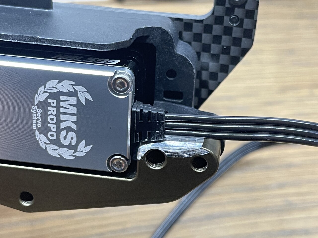
Depending on your servo, your throttle servo wire may touch the servo mount.
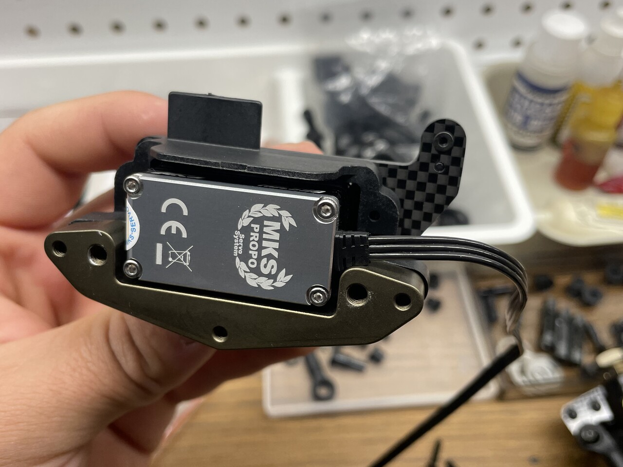
In order to remove this clash, you can remove material from the aluminium mount as below:
¶ Fuel tank tube build
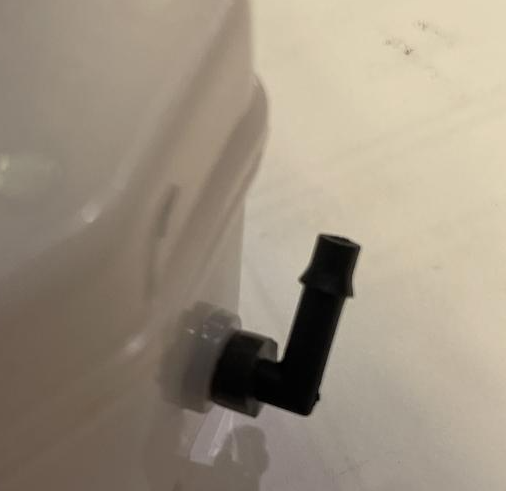
The fuel tank arrives with excess tubing on the clunk.
Build tip from Tony Scarsella:
Measure where you want the clunk. Then cut of fuel line at 3-3.5mm out side. Pull out cut line to 5-6mm,wet the elbow, start lightly pushing in elbow while rotating. Maybe 20-30 seconds, lightly push elbow into line. Twist and light pressure will seat elbow flare, just inside tank. May take a couple tries, light pressure and twist is key.
¶ Front arm modification for Procircuit wheels
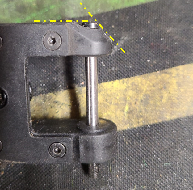
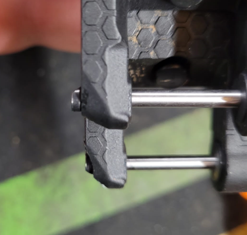
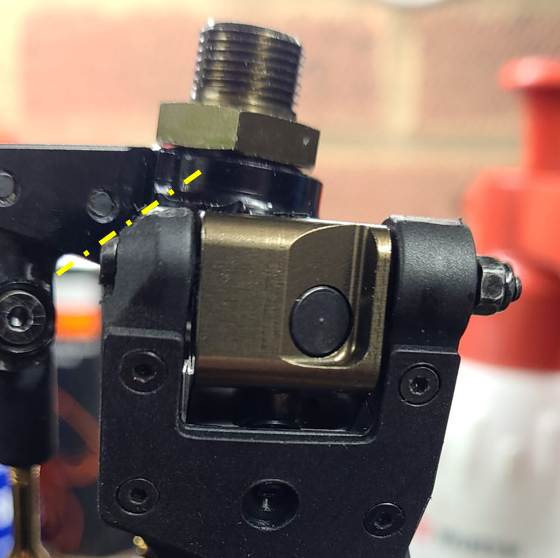
Procircuit V2 wheel internal webbing has been seen to rub on the back of the front arms. To mitigate this Rob Cockcroft came up with a simple mod to achieve full lock.
- Recess the arm until the head of the hingepin is flush with the arm (roughly 2mm)
- Create a 45deg chamfer on the arm and hingepin head. Note that the hingepin will then have an orientaion.
Modification process - bolt head flush with arm, 45deg chamfer:
New vs modified arm:
Assembled with mod:
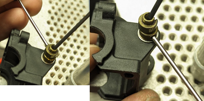
¶ Easy removal of knuckle bushings
Curtis Wong said: If you're having trouble getting the bushings out of the knuckles a m3 socket cap and flanged nut work well to extract it without gouging anything. Hold the nut with a wrench and unscrew the screw through the bushing center.
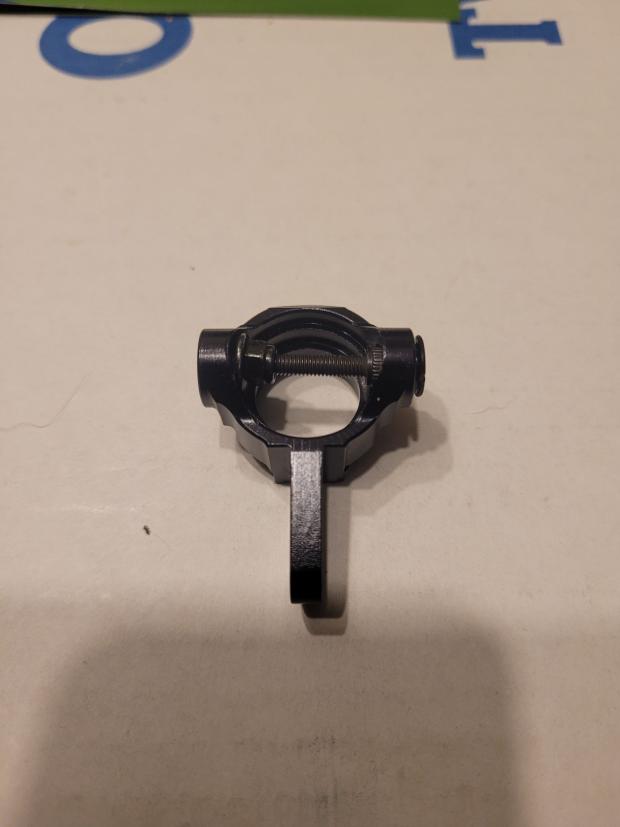
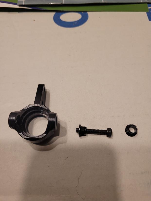
¶ Upper rear arm position with 1.5 toe in
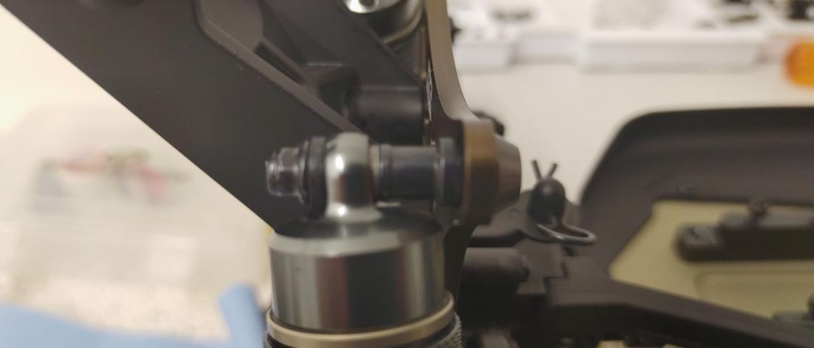
When running the 1.5 toe in C and D block with the rear hubs in the center you will need to move the upper arms 1mm forward to get the link to slide in the hub freely.
¶ Easy battery removal
Nio Chieffo said: A little tip, using a scotch tape around the battery with a little flap will help you to remove them
¶ Easy pill insert removal
Back in the day when Joseph designed the JQRacing Black Edition he developed a way to easyily remove the pill inserts in the ABCD blocks. This method can also be used in the Mayako MX8.
Link to the video: https://www.youtube.com/watch?v=J8r7qj02MtA
¶ Rear Shocks binding
The rear shock can bind up a little when mounted the same front. This can stop the rear squatting and will wear in during use, but you can build it to be free during first build.
Longterm Fix:
Use MYB0138-ALU - Aluminium Short Shock Stand-Off for Rear 4pcs for Mayako MX8 (-22)
Temporary Fix:
Mike Walker said: Put two clutch bell shims on each stand off. Put the shock on and then put the shock bushing on backward (moving the shock forward a small amount) Install nut and shocks are free
¶ Engine Forward modification
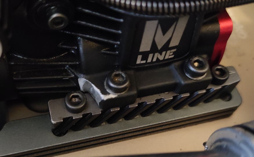
With some engines, the casing must be modified in order to run in the engine forward position. The mounting ears should be dremelled in order to clear the bolt heads.
And example of this on the Ultimate M3X 2.0 is shown below (note engine in the picture is in the backward position):
¶ Centre Diff removal
Felix Koegler has put together a short video explaining how he removes and reinstalls the centre diff assembly.
¶ Second mounting hole rear brace
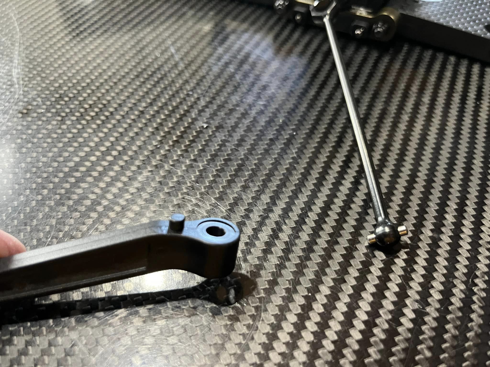
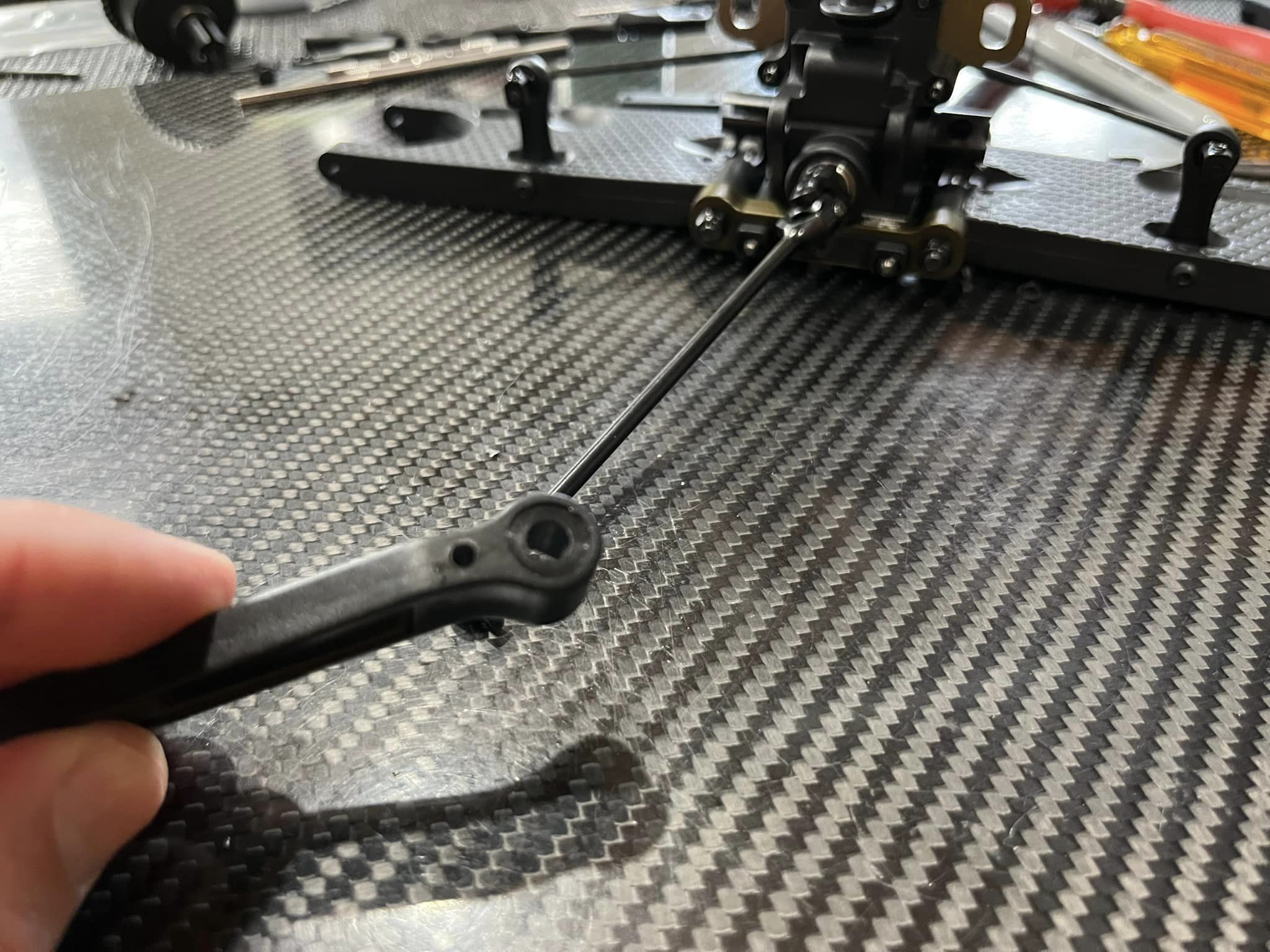
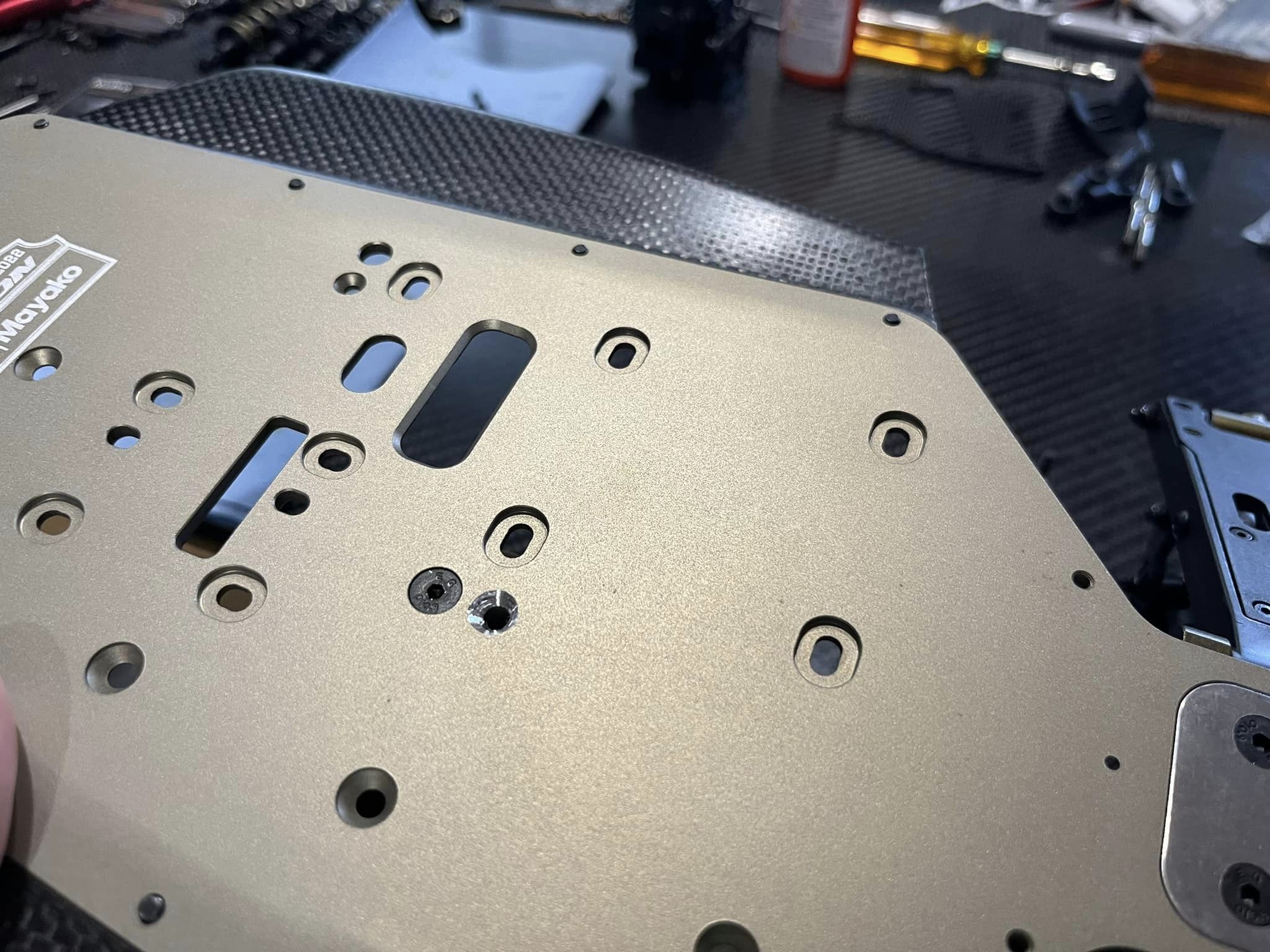
Jared Tebo found a way to make a second mounting hole for the rear brace to increase it's strength if needed. Pictures below show the process
Cut of the plastic pin
Drill an extra M3 hole
Countersink the hole in the chassis
¶ Setup optimal brake lever travel
In the video below Robert Batlle is showing the optimal brake lever travel needed for the best brake performance.
¶ Swaybar fitting
Learned a trick today while building a car up. The sway bars are difficult to keep moving free in the bearing supports because of the way the collars are designed. When you tighten the M3 setscrew, it twists the collar enough to cause misalignment between the two bearings. After thinking about this (and struggling EVERY time to get them feeling “just right”) I came up with an easy solution. You need 1 extra sway bar collar (or a drilled out linkage collar) and set screw to do this setup procedure, and I replicated it 5 times in a row on multiple diff case covers and sway bars with perfect results every time.
So here we start, with the parts we will be assembling. Not shown: the extra sway bar collar.
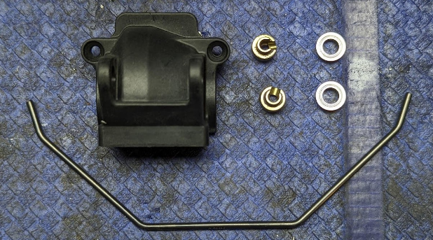
Begin by installing the two 5x8mm flanged bearings in the diff cover and threading the sway bar through them as normal.
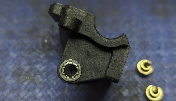
You can also slide the two collars over the bar and up into the bearings. This part is important, as this is where you “center” the bar on the diff cover. I eyeball this, as long as it’s close (within a millimeter or two) it should be fine. Once happy with how the bar is centered, ensure the collars are all the way in the bearings, and snug only 1 of them up with your 1.5mm hex driver. This will ensure the bar stays centered through the next steps.
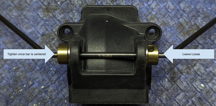
Since you only snugged one collar down, start with the one that is loose, and install a second sway bar collar next to it with the bearing nubbin facing away from the diff case cover. On this rear sway bar, the notch in the collar only faces one direction since it will sit in the bend in the bar. Push the extra collar against the inner collar that is loose and tighten the setscrew on the extra outer collar.
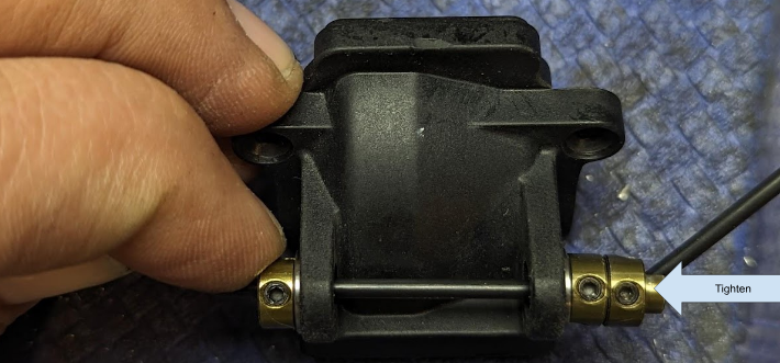
Now that the extra collar is tightened on the sway bar, you can tighten the “loose” collar you backed the extra collar up against. This extra collar prevents it from twisting on the bar when you tighten the set screw. Remember to threadlock the set screw on the inner collar, and I like to orient them so the screws face straight up so that they don’t get packed with mud and are easy to access when the sway bar is connected to the arms. Once the inner collar is tightened, you can remove the extra collar and move it to the other side. You should also loosen the first collar that we tightened earlier at this time. If you play with the sway bar with both collars tight at this point, you’ll notice that it is a bit “sticky” and doesn’t move as freely as it should. This last step will fix this.
I like to set the cover up on my car stand, so that I can push on the extra collar as I tighten it against the now loosened collar on the other side. From here we repeat the process, pushing down gently on the “extra” collar while tightening it, then tightening the inside collar with threadlock with the set screw in the preferred orientation.
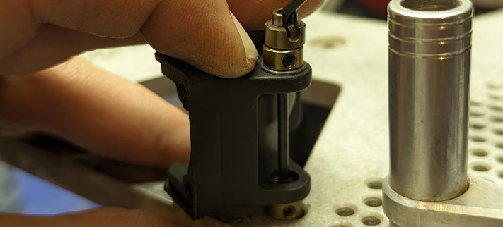
Once complete, you should have a sway bar that is centered on the diff cover, AND moves freely enough to wiggle when you move the case and falls under its own weight easily. Remove the extra collar and assemble!
